Paraffinising plant
The proposed plant will essentially consist of the following functional units:

One cycle, three units
The proposed plant will essentially consist of the following functional units.
Storage tank
Insulated and heated stainless steel buffer tank for liquid paraffin, or insulated and heated melting tank for solid paraffin.
Distribution ring
Ring-type paraffin distribution system to the three line paraffin units.
Paraffin machines
The three line paraffin units:
Low fluteHigh fluteHigh flute cover
Working paper width
Resettable dosing settings
Operating capacity of the external silo
Stainless steel of the tank
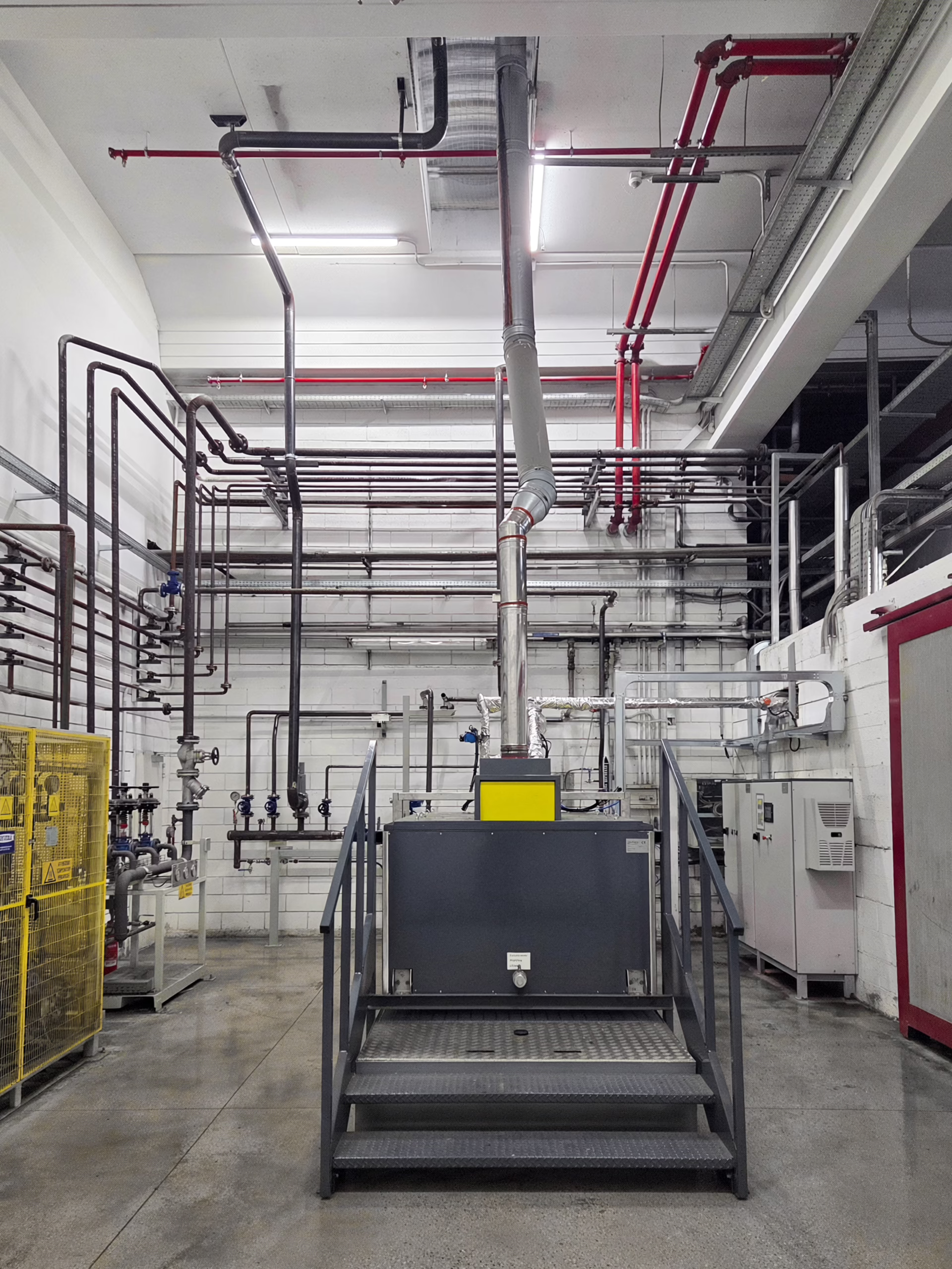
Paraffin units
The proposed paraffin units have the following characteristics:
Hot paraffin applicator using a chrome-plated and rubber-coated roller
Working paper width: 2800 mm
Automatic reading of the paper width and consequent change of working settings
Movement of paraffin distribution limiters to change the paraffin coating band for combined orders, including those without paraffin
Variable-speed Taker cylinder motor to change the paraffin dosing, with ten different resettable settings
Preheated paraffin rollers with a function preventing paraffin from adhering and sticking to the rollers
Rollers for correct paper path and tensioning
Circular anti-residue stainless steel tank
Touch screen control panel, customizable according to the customer's needs
Paraffin distribution ring
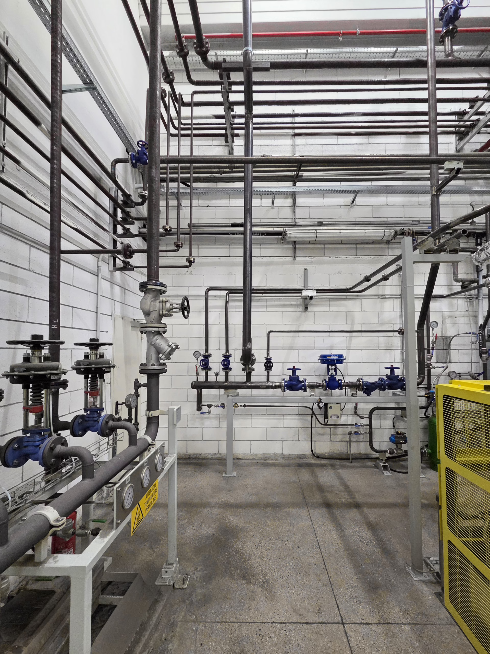
The distribution ring will supply the necessary amount of paraffin to the three paraffin units and keep it at the set temperature conditions.
It will keep the paraffin constantly moving by means of a circulation pump. At the end of work, through a series of valves and appropriate modulation of the local pumps of the individual paraffin units, the entire circuit and the paraffin units themselves can be emptied automatically, with the residual paraffin returned to the buffer tank.
This will allow, besides considerable energy savings, a reduction in the time needed to restart the plant.
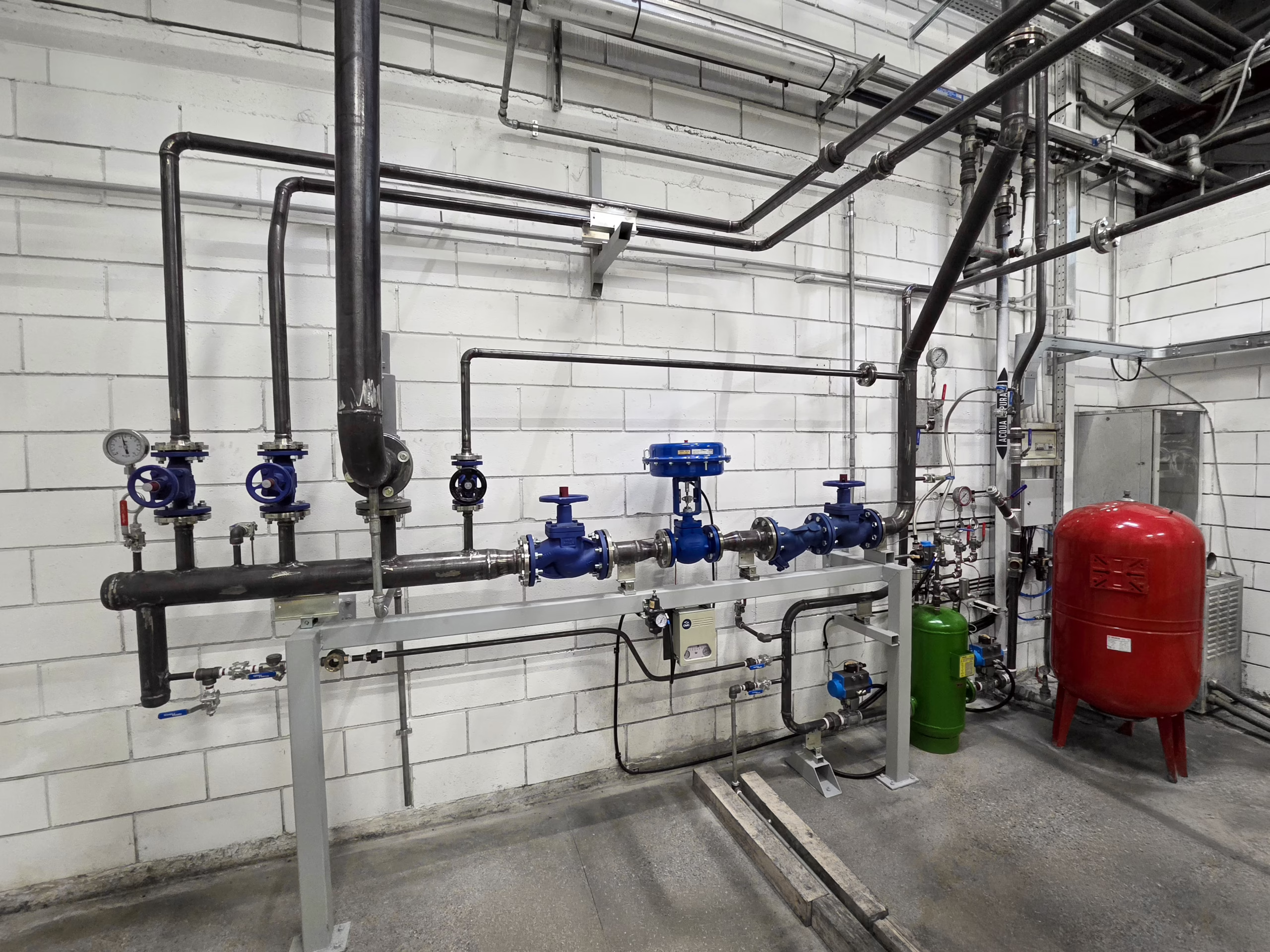
Storage silo with buffer tank or melting tank
The paraffin distribution system will be supplied with a storage silo with buffer tank, or a melting tank, depending on the customer's production needs.
Silo with buffer tank
In the first case, the larger tank, located outside the structure, will be used to store paraffin for long-term reserves. Its operating capacity will be approximately 40 m³. It will be made of AISI 304 stainless steel.
The smaller tank, located inside the structure, which will also contain the steam reduction circuits and the distribution manifold, will act as a disconnector between the plant and the main storage silo.
It will be used to manage the amount of paraffin required for each production cycle and will be refilled each time. The filling, automatically regulated, will be such that the free volume is always sufficient to keep all the product in circulation both in the distribution ring and in the collection tanks of the paraffin units.
This allows the plant to be completely emptied at the end of the shift.
Melting tank
In the second case, the tank will be used to store molten paraffin and will also contain the steam reduction circuits and the distribution manifold.
The tank will also be used to manage the amount of paraffin required for each production cycle and will be refilled each time.
The filling, manually regulated by the operator, will be such that the free volume is always sufficient to keep all the product in circulation both in the distribution ring and in the collection tanks of the paraffin units.
The plant in pictures